Initated: 01/08/2024
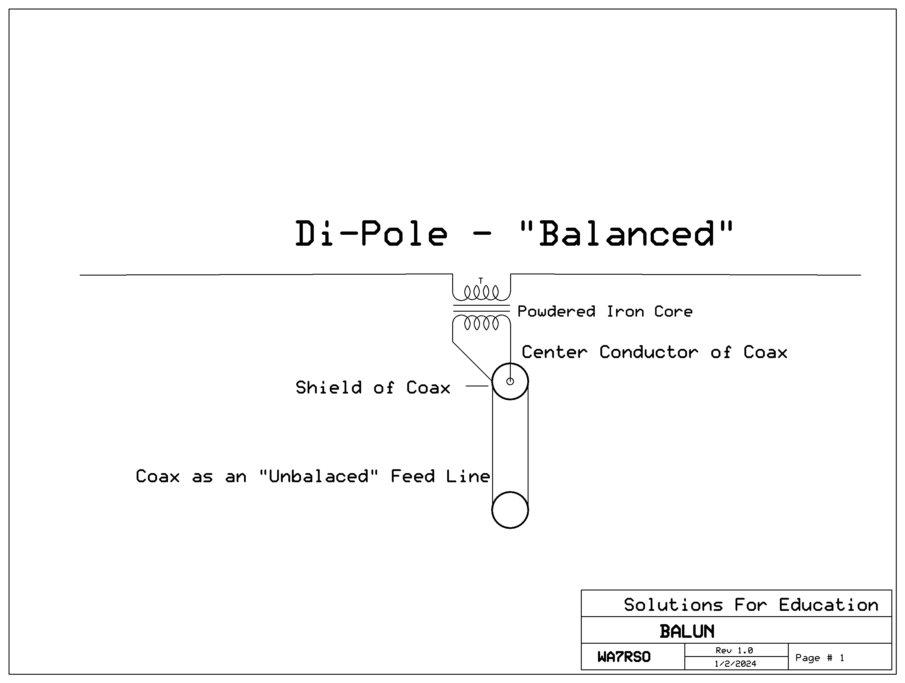
BALUN,
i.e. BAL-UN,
i.e. BALanced-to-UNbalanced:
Why consider using a BALUN in the first place, since it is possible to simply terminate the coax at a plastic coupler to the dipole leads, and it does work. After all, if it does work, why fix it? Well one simple explanation is that the coax becomes part of the antenna, rather than just feeding the antenna. A little more complicated explanation is regarding the Impedances and Currents involved at the feed point. To make a long story short, it also affects the radiation patter slightly.
I should also make mention of the great wealth of information in the "ARRL Antenna Book". I believe that the latest one I have is the >800 page "19th Edition", with a CD-ROM. There are a number of other types of BALUN's illustrated and discussed.
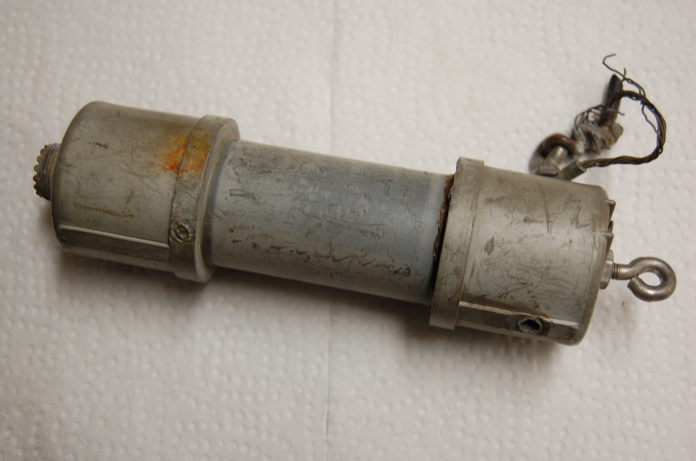
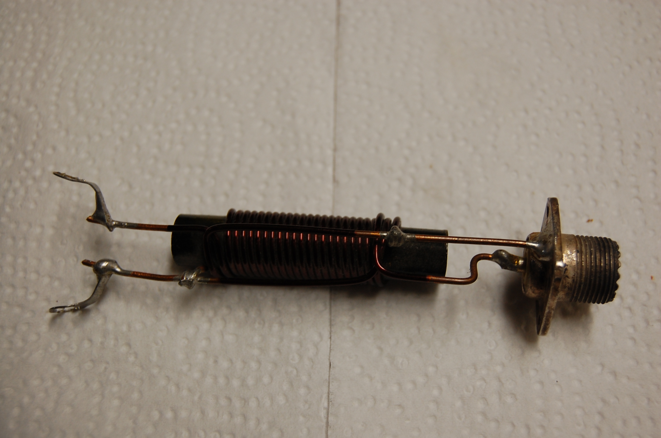
In my early years of Ham Radio, I very seldom did any VHF or UHF, and did a lot of experimenting with wire antennas for best match at the CW portions of the HF Bands. My favorite BALUN was the simple store-bought “Voltage BALUN”, such as this one. A few of my wire antennas were simple dipoles, but almost always were various “Inverted-V's”, or even “Horizonal-V's”. Especially because they had a basic 50 Ohm feed point instead of the 72 to 75 Ohm feed point, and they were not only quieter, but was almostOmni-Directional.
When one of my BALUN's failed, I found it easy to repair them with new PVC plastic pipe. On the one shown here, I decided to keep it for display for other folks as a good illustration. So even though it is many years old, it is still very useful for display.
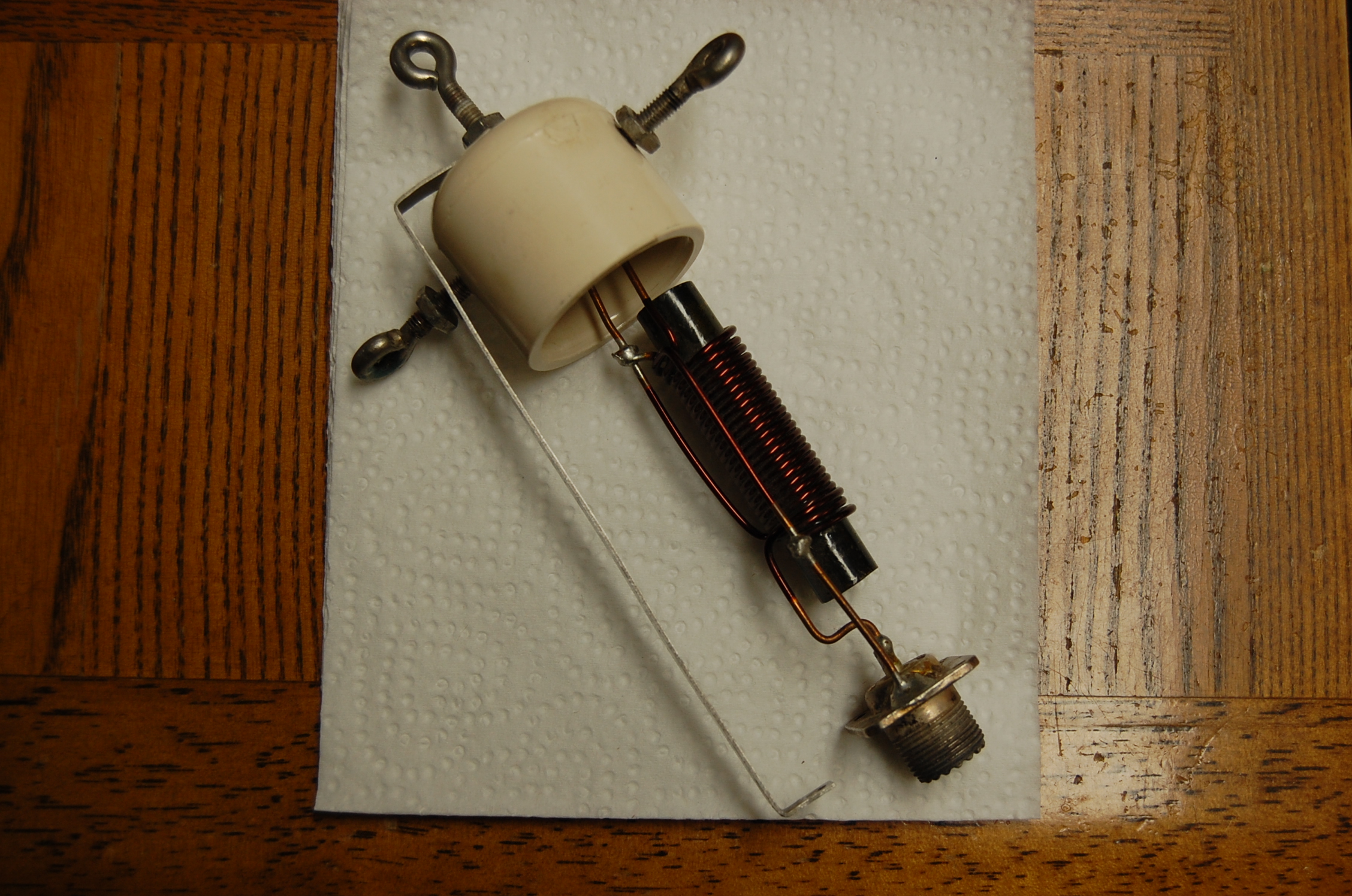
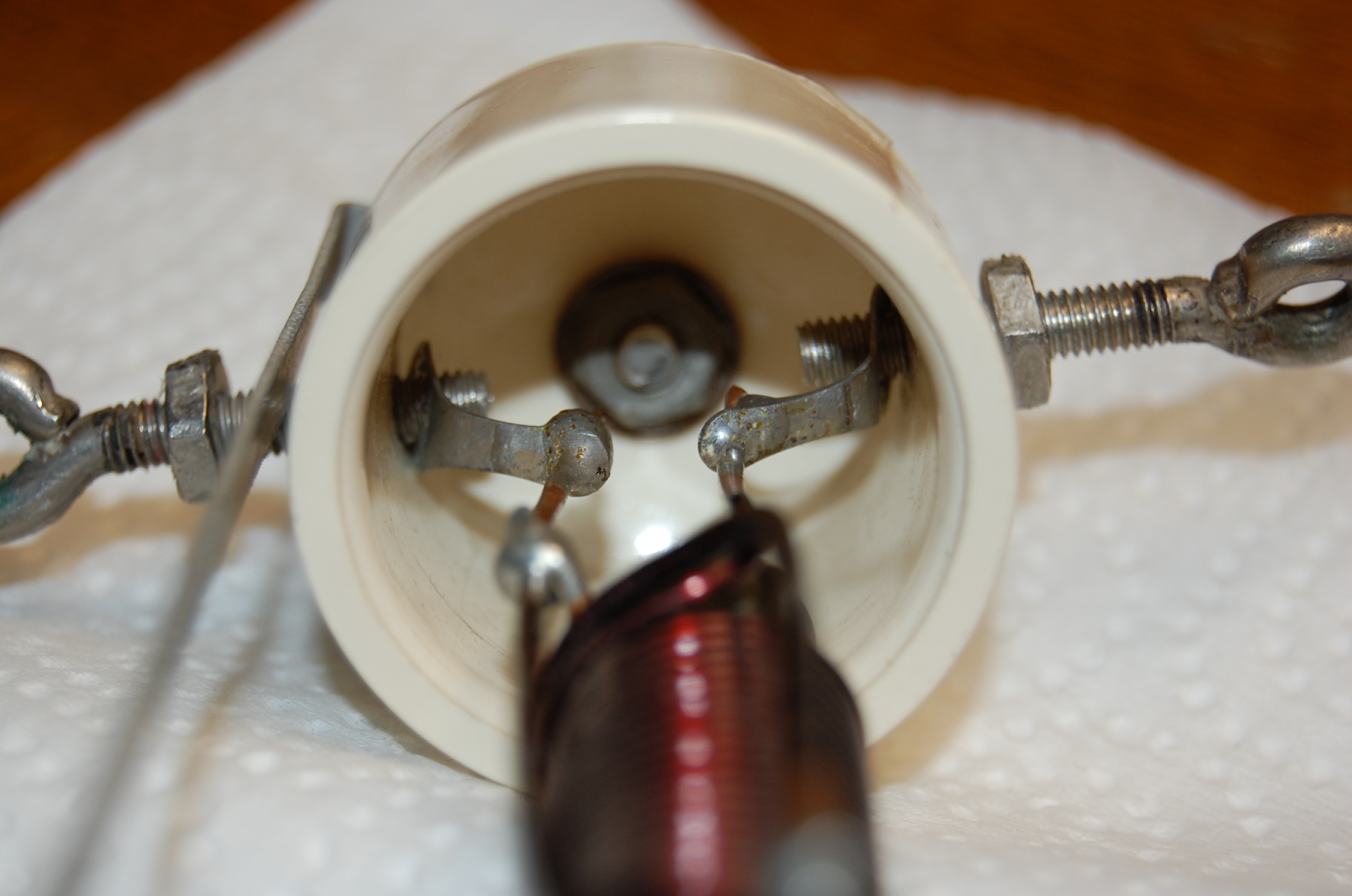
This type of BALUN is often refered to as a “Voltage BALUN”, due to it’s transformer (schematical illustration) “Turns-Ratio” characterestics. (see physical illustration). In this regard, a “Coil Toroid” can be used as well, (the dipole connections inside the top cap).
The transformer input windings are isolated electrically from the transformer output windings, but transfers energy via electro-magnetic coupling from primary to secondary.
While power is transferred from input to output, the winding may be on simply a 1:1 ratio for equal Impedance's of Source to Load.
In the case of a dipole (Balanced Load), with the Characteristic Impedance of say 75 Ohms, to be fed with a 50 Ohm Coax (Unbalanced Feed Line), a 1:1 turns-ratio would result in a slight “Miss-match”, for full power transfer (SWR of 1.5, but useable).
For only voltage considerations, if the primary had 50 turns, with 50Volts applied, and the Secondary had 75 turns, the secondary would develop 75 Volts, but with less current than the primary, for the same wattage (power).
The same would be true if the primary had 5 turns of larger wire and the secondary had 7.5 turns of the same heavy wire. (Notice the interwoven windings)
Heavy wire for both the primary and secondary windings would be used to avoid IR Losses, and would be insulated to avoid shorting electrically to other windings.
Although “Air-Core” couplings between the primary and secondary windings would be required for VHF or UHF, at lower frequencies such as at HF, the Permeance of iron particles bonded together, works for efficient coupling (see physical illustration). Remembering that iron has permeance of 1,000 to 1, compared with air. (Magnetic Field enhancement)
For a transformer consideration, remember that the “Reflected Impedance Ratio” is the “Square of the Turns Ratio”, so actually, only a slight 1.2247 turns-ratio is required for a Ohms match of 50 ohm to 75 ohms, being the real load-match consideration.
Next: How to “Bench Test” this type of BALUN
. . I will illustrate that with simply any Antenna Testor . .
Dave - WA7RSO